Casting Simulation Software to Reduce Casting Defects
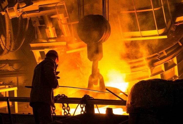
Learn how casting simulation software uses FEM-based modeling to predict casting defects, optimize filling and solidification, and reduce scrap before production.
Understanding Casting Simulation
Casting simulation is the use of numerical modeling — typically based on Finite Element Method (FEM) or Finite Difference Method (FDM) — to digitally replicate the casting process before any physical tooling is made. The software models how molten metal flows into a mold cavity, how heat transfers through the system, where solidification begins and progresses, and where stresses build up during cooling.
By solving the governing equations of fluid dynamics, heat transfer, and solid mechanics simultaneously, simulation software predicts exactly where defects are likely to form — shrinkage porosity, gas inclusions, hot tears, cold shuts — and allows engineers to intervene at the design stage rather than the production floor.
The key inputs include alloy material properties, mold geometry, pouring temperature, gating system design, and process parameters. The software outputs visualizations of mold fill, solidification progression, temperature gradients, and defect probability maps.
Key Simulation Outputs
- Mold filling animation and flow visualization
- Solidification sequence mapping
- Temperature gradient analysis
- Shrinkage and porosity prediction
- Hot spot and cold shut detection
- Thermal stress and distortion analysis
- Residual stress distribution
Why This Matters to Modern Foundries and Engineers
Defect-Related Scrap
Typical scrap rates in foundries without simulation-driven process validation
Earlier Detection
Problems caught during simulation rather than after first pour, avoiding tooling rework
Cost Multiplier
Cost of correcting a defect increases at each downstream stage of production
Casting is one of the oldest manufacturing processes in human history, yet it remains one of the most technically demanding. Thin sections solidify faster than thick ones. Gating design determines whether metal arrives in the cavity with laminar or turbulent flow. Riser placement determines whether shrinkage occurs inside the casting or safely inside the riser. These interdependencies are difficult to optimize through intuition alone — and the consequences of getting it wrong are expensive.
Common Challenges Foundry Engineers Face
Even experienced foundry engineers and casting designers encounter recurring problems that traditional trial-and-error methods struggle to prevent reliably.
Shrinkage Porosity
As molten metal solidifies and contracts, isolated pockets of liquid metal become cut off from the feeding system. The resulting internal voids compromise mechanical integrity and often go undetected until non-destructive testing or machining reveals them — after significant value has been added to the part.
Cold Shuts and Misruns
When two metal fronts meet without fully merging, or when the metal freezes before completely filling the cavity, the result is an incomplete or structurally weak casting. These defects are strongly tied to pouring temperature, flow velocity, and gating design — all parameters that simulation can optimize.
Gas Porosity and Inclusions
Turbulent metal flow entrains air and gases, which become trapped as the metal solidifies. Mold outgassing adds further complexity. Without flow simulation, predicting where gas entrapment will occur requires extensive physical trial work.
Hot Tears and Thermal Cracking
Differential thermal contraction during solidification creates internal stresses. In geometrically complex castings, these stresses can exceed the alloy's strength in the semi-solid state, producing hot tears that may or may not be visible on the surface.
Inefficient Gating and Risering
Oversized risers and complex gating systems waste material and add machining cost. Undersized risers fail to feed solidification shrinkage. Optimizing these systems without simulation typically requires multiple expensive physical trials.
Late-Stage Discovery
Without simulation, defects are discovered after tooling is complete and production has started. At this stage, even minor design changes require significant rework of patterns, dies, or molds — and schedule delays cascade through the supply chain.
Traditional Trial-and-Error vs. Simulation-Driven Design
The contrast between conventional foundry practice and a simulation-driven workflow is significant — not just in outcomes, but in the fundamental engineering logic applied to the problem.
| Consideration | Traditional Approach | Simulation-Driven Approach |
|---|---|---|
| Defect Detection | After first physical pour | Before any tooling is made |
| Design Iteration | Physical trial-and-error | Virtual parametric studies |
| Time to First Good Part | Multiple casting trials | Reduced trials, faster convergence |
| Gating/Riser Optimization | Experience and heuristics | Quantitative simulation data |
| Knowledge Retention | Relies on individual expertise | Documented simulation records |
| Cost of Design Changes | High — tooling already committed | Low — changes made digitally |
The shift is not simply about adopting new software. It represents a change in when engineering decisions are made — moving critical problem-solving from the shop floor back to the design office, where changes are fast and inexpensive.
How Casting Simulation Software Works in Practice
Geometry Setup
Import CAD, define alloy, mold, and process parameters.
Numerical Simulation
Run FEM/FDM solver for fluid flow and heat transfer.
Results Analysis
Inspect mold fill, porosity, thermal, and stress maps.
Design Optimization
Adjust gating/risers or geometry and re-run simulation.
What Engineers Can Evaluate
- Alternative gating system configurations
- Riser size, placement, and geometry
- Pouring temperature and speed sensitivity
- Chilling strategies to control solidification sequence
- Mold material effects on heat extraction
Supported Process Types
- Sand casting (green sand, resin-bonded)
- Die casting (gravity and high-pressure)
- Investment casting
- Permanent mold casting
- Lost foam and lost wax processes
A Practical Scenario: Applying Simulation to a New Casting Design
Hypothetical Example
The following scenario is illustrative. It represents a realistic application of casting simulation methodology and is not based on a specific CSoft customer or project.
An engineering team is tasked with developing a new aluminum structural bracket for an industrial equipment manufacturer. The part has varying wall thicknesses — thin ribs connecting heavier boss sections — a configuration known to create differential solidification rates and shrinkage risk.
Using casting simulation software, the team imports the CAD geometry, defines the aluminum alloy properties and mold material, and sets up an initial gating and risering configuration based on standard practice. The first simulation run immediately reveals two isolated hot spots in the thicker boss sections, where liquid metal will become isolated during solidification — a clear indicator of shrinkage porosity risk.
What Simulation Changes
Rather than pouring a physical test casting, the engineering team makes three virtual design modifications:
- 1 Relocating and enlarging one riser to improve feeding of the isolated hot spots
- 2 Adding a local chill at one boss section to accelerate solidification and shift the hot spot into the riser
- 3 Modifying the gating entry point to reduce turbulence and improve metal distribution
A second simulation run confirms that the hot spots have been eliminated and fill behavior has improved. The team commits to tooling with significantly higher confidence than a traditional trial-and-error approach would provide. When the first physical casting is poured, it meets dimensional and integrity requirements with no shrinkage-related rework required.
Key Benefits of Casting Simulation in Production Environments
Reduced Scrap and Rework
By identifying and correcting defect-prone conditions before production, simulation directly reduces scrap rates and the cost of internal rework — improving yield and material efficiency.
Faster Time-to-Market
Simulation compresses the new product introduction cycle by reducing the number of physical casting trials required to achieve a good part. Fewer trials means faster ramp-up to volume production.
Lower Tooling Risk
Committing to tooling — patterns, dies, or molds — after simulation validation significantly reduces the risk of expensive tooling rework driven by process-related defects discovered in initial production.
Better Engineering Documentation
Simulation results create a documented engineering record of process development decisions — valuable for quality audits, process transfers, and troubleshooting future production issues.
Optimized Yield and Material Use
Simulation enables engineers to right-size risers and gating systems — reducing metal consumption, minimizing secondary machining, and improving overall casting yield without compromising quality.
Choosing the Right Casting Simulation Software
Selecting a casting simulation platform is a significant technical and commercial decision. The following criteria help engineering teams evaluate options objectively and select a solution aligned with their actual operational requirements.
Simulation Accuracy and Physical Models
Evaluate the numerical methods underpinning the software. FEM and FDM-based solvers with well-validated material databases produce more reliable predictions. Ask vendors about validation studies and how the software handles your alloy systems and process types.
Process and Material Coverage
Confirm that the software supports the specific casting processes and alloy families relevant to your facility. A platform optimized for high-pressure die casting may not be equally well-suited for investment casting or sand casting operations.
CAD Integration and Geometry Import
Simulation workflows start with geometry. Evaluate how well the software imports CAD data from your existing design tools, handles complex geometries, and generates simulation-ready meshes without excessive manual preparation.
Usability and Learning Curve
Consider the practical usability for your engineering team. Software that requires weeks of specialized training before producing useful results delays the return on investment. Evaluate the interface, pre-processing workflow, and availability of training resources.
Vendor Support and Software Longevity
Assess the vendor's track record, active development roadmap, and quality of technical support. Casting simulation software is a long-term investment — you need a vendor who will support the product and respond to technical queries over the life of the platform.
Conclusion: Simulate First, Pour with Confidence
Casting defects are not an inevitable cost of doing business in a foundry. They are, in large part, an engineering problem — one that can be addressed at the design stage rather than the production floor, provided engineers have the right tools.
Casting simulation software gives foundry engineers and casting designers the ability to test process configurations digitally, identify defect risks quantitatively, and make informed decisions before any metal is poured. The result is fewer scrapped parts, faster qualification of new designs, better use of tooling investment, and a more systematic approach to process development.
For engineering teams ready to move beyond trial-and-error and adopt a simulation-driven approach to casting quality, CSoft's PoligonSoft provides a focused, numerically rigorous platform built specifically for this purpose. Explore PoligonSoft's capabilities or contact CSoft to discuss how casting simulation can fit into your engineering workflow.




0 Comments
What do you think?
Please leave a reply. Your email address will not be published. Required fields are marked *